Bits and pieces...
This is more of a engineer's scrapbook containing some more technical musings, as well as pics and diagrams from my early construction attempts. (more to come)
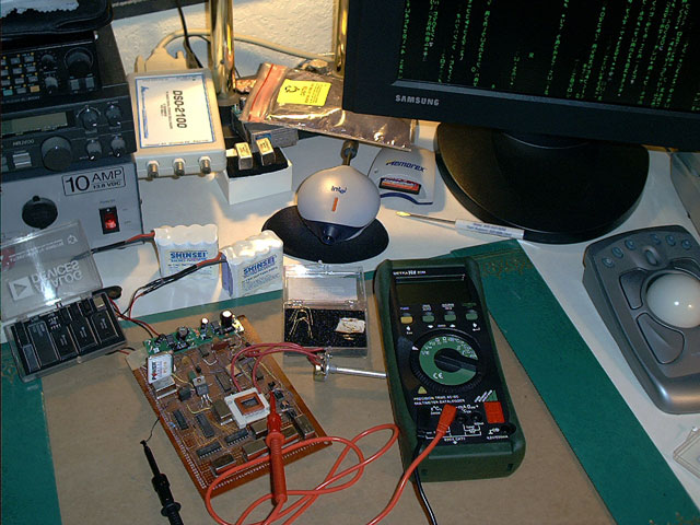
This picture shows some work on a first generation transmission subassembly. The input signal is conditioned in the multiple stage processor boards in green, then injected into the P2 wave DMC section, which comprises the circuitry on the brown board. The DMC shown in this picture is of the dynamic type, which contains the mixer stage as well as the stages required to translate the signal from the complex domain to the imaginary domain. While not shown in this first gen prototype, the entire circuit along with the complex waveform generator (not shown) is completely encased in a shield that makes an effective Faraday cage in order to minimize noise figures.
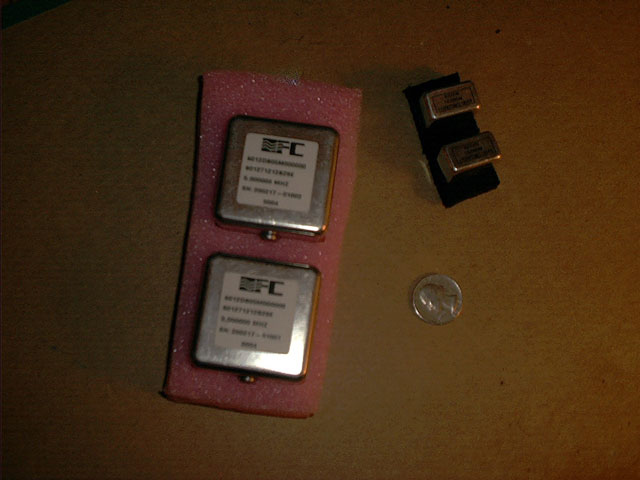
Much design work goes into the oscillators needed to generate a superluminal signal. While clock signals in other parts of the circuit may be cheap, computer grade square waves, this is not the case with the waveform needed within the DMC. The required signal generation must be high precision, low noise. Here are two examples. They both generate precision sine waves, but the smaller units have a noise figure of -65DbC @1 Hz and were not successful in creating a stable waveform. Noise prevented a stable P2 waveform from being generated. The larger double oven units were designed specifically to overcome the problem of close in phase noise. These units provided a minimum noise figure of -107DbC @ 1 Hz, and were successful in generating the proper environmental conditions necessary for making a useful P2 wave within the decision making circuitry (DMC). Presently, this is the largest problem to be overcome before superluminal communication can be considered a commodity industry. First, as you can see by looking at the U.S. Quarter, these oscillators are huge. The rest of the circuitry can, and has been in subsequent prototype generations, shrunk considerably in size through the use of micro power CMOS and SMT components. But, these oscillators must be physically large to work properly and they make for a bulky, power hungry design (each oscillator consumes 0.5 amp @ 12 Volts). Also, being rated for use in spacecraft, you will need to sell your family car to get them... and don't forget you need two. A matched pair - one for the transmitter and one for the receiver.
I can say a lot more about waveform generation... it is because of the huge size of these things that a 'Star Trek' style portable communicator does not exist today. The entire rest of the device can, at the present sixth generation, easily fit into a cell phone sized package, but you will look strange hanging a briefcase sized unit holding the crystal technology around your neck, not to mention the car battery needed to power it all up. Still Geek tech. Definitely not yet a Chick Magnet. Oh well...
![]()